User Guide
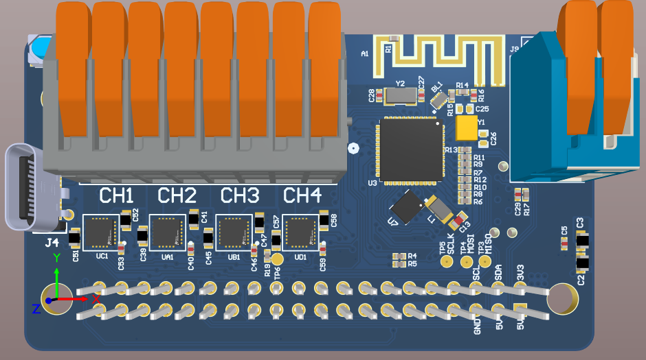
Hardware Overview
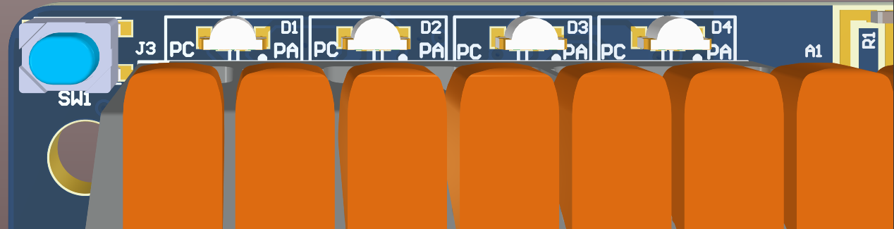
BLE Role Selection
The device boots as a BLE Central device after POR by default. D1 will be BLUE.
Press and hold push button (SW1) during POR to boot as a BLE Peripheral Device. D1 will be GREEN.
BLE Central Role
LED States
BLUE
OFF
OFF
OFF
Idle
BLUE
BLUE
OFF
OFF
Scanning
BLUE
BLUE
BLUE
OFF
Paired
BLUE
BLUE
BLUE
BLUE GREEN
Bond Saved
BLUE
BLUE
BLUE
BLUE
Encrypted Pair
BLE Peripheral Role
LED States
GREEN
OFF
OFF
OFF
Idle
GREEN
GREEN
OFF
OFF
Advertising
GREEN
GREEN
GREEN
OFF
Paired
Unsolicited Data Characteristic
This characteristic is used to send telemetry data to the host via BLE notifications. Each 20-byte notification has the following format:
0
Packet ID
Describes the contents of the Data Byte Field
1
Packet Index
Rolling counter. Packets with equal Packet Indices are from the same sample interval
2
Data Byte 0
Refer to dedicated section
...
19
Data Byte 17
Unsolicited Data notifications will be sent out at a rate of 1 Hz. Frames with equivalent Packet Indices will have an inter-frame delay of 100 ms between them.
Packet ID 1 Data Bytes
This packet contains the raw IMU data and TOF distance measurement in mm (if active).
0
Accel X LSB
int16
1
Accel X MSB
2
Accel Y LSB
int16
3
Accel Y MSB
4
Accel Z LSB
int16
5
Accel Z MSB
6
Gyro X LSB
int16
7
Gyro X MSB
8
Gyro Y LSB
int16
9
Gyro Y MSB
10
Gyro Z LSB
int16
11
Gyro Z MSB
12
TOF Distance LSB (mm)
uint16
13
TOF Distance MSB (mm)
14
Reserved
15
Reserved
16
Reserved
17
Reserved
IMU Data Conversion
The following code snippets show how to convert the raw int16 accelerometer and gyroscope data to their respective units:
Accelerometer full-scale: +/- 8g
Gyroscope full-scale: +/- 500 dps
Packet ID 2 Data Bytes
This packet contains the motor current measurements in A.
0
Motor 1 Current XLSB
float
1
Motor 1 Current LSB
2
Motor 1 Current MSB
3
Motor 1 Current XMSB
4
Motor 2 Current XLSB
float
5
Motor 2 Current LSB
6
Motor 2 Current MSB
7
Motor 2 Current XMSB
8
Motor 3 Current XLSB
float
9
Motor 3 Current LSB
10
Motor 3 Current MSB
11
Motor 3 Current XMSB
12
Motor 4 Current XLSB
float
13
Motor 4 Current LSB
14
Motor 4 Current MSB
15
Motor 4 Current XMSB
16
Reserved
17
Reserved
BLE Commands
The following table outlines BLE commands supported by the Rover. Refer to respective section for more information.
**Legacy MotorHAT BLE commands.
Set Motor 1 Throttle
Command: 0x0003
Mailbox:
Byte 0:
Description: Motor Throttle
Range: -100 to 100, inclusive
Type: int8
Command Response(s)
MDRDIOPROFILE_CMDRSP_SUCCESS
MDRDIOPROFILE_CMDRSP_INV_PARAM
MDRDIOPROFILE_CMDRSP_FAILURE
Set Motor 2 Throttle
Command: 0x0004
Mailbox:
Byte 0:
Description: Motor Throttle
Range: -100 to 100, inclusive
Type: int8
Command Response(s)
MDRDIOPROFILE_CMDRSP_SUCCESS
MDRDIOPROFILE_CMDRSP_INV_PARAM
MDRDIOPROFILE_CMDRSP_FAILURE
Set Motor 1 and 2 Throttles
Command: 0x0005
Mailbox:
Byte 0:
Description: Motor 1 Throttle
Range: -100 to 100, inclusive
Type: int8
Byte 1:
Description: Motor 2 Throttle
Range: -100 to 100, inclusive
Type: int8
Command Response(s)
MDRDIOPROFILE_CMDRSP_SUCCESS
MDRDIOPROFILE_CMDRSP_INV_PARAM
MDRDIOPROFILE_CMDRSP_FAILURE
Kill All Motors
Command: 0x0007
Command Response(s)
MDRDIOPROFILE_CMDRSP_SUCCESS
MDRDIOPROFILE_CMDRSP_FAILURE
Set Peripheral State
Enables/disables optional on-board/off-board peripherals.
State stored in NVM. Default: All peripherals disabled.
If successful, device performs a power-on-reset (POR) after 500 ms.
Command: 0x000D
Mailbox:
Byte 0:
Description: Peripheral ID
Range:
Supported ID(s)
0x00: MODI
Type: uint8
Byte 1:
Description: Peripheral State
Range:
0 (dec): Peripheral disabled
1 (dec): Peripheral enabled
Type: uint8
Command Response(s)
MDRDIOPROFILE_CMDRSP_SUCCESS
MDRDIOPROFILE_CMDRSP_INV_PARAM
MDRDIOPROFILE_CMDRSP_FAILURE
Set Motor 3 Throttle
Command: 0x0010
Mailbox:
Byte 0:
Description: Motor Throttle
Range: -100 to 100, inclusive
Type: int8
Command Response(s)
MDRDIOPROFILE_CMDRSP_SUCCESS
MDRDIOPROFILE_CMDRSP_INV_PARAM
MDRDIOPROFILE_CMDRSP_FAILURE
Set Motor 4 Throttle
Command: 0x0011
Mailbox:
Byte 0:
Description: Motor Throttle
Range: -100 to 100, inclusive
Type: int8
Command Response(s)
MDRDIOPROFILE_CMDRSP_SUCCESS
MDRDIOPROFILE_CMDRSP_INV_PARAM
MDRDIOPROFILE_CMDRSP_FAILURE
Set Motor 3 and 4 Throttles
Command: 0x0012
Mailbox:
Byte 0:
Description: Motor 3 Throttle
Range: -100 to 100, inclusive
Type: int8
Byte 1:
Description: Motor 4 Throttle
Range: -100 to 100, inclusive
Type: int8
Command Response(s)
MDRDIOPROFILE_CMDRSP_SUCCESS
MDRDIOPROFILE_CMDRSP_INV_PARAM
MDRDIOPROFILE_CMDRSP_FAILURE
Set All Motor Throttles
Command: 0x0013
Mailbox:
Byte 0:
Description: Motor 1 Throttle
Range: -100 to 100, inclusive
Type: int8
Byte 1:
Description: Motor 2 Throttle
Range: -100 to 100, inclusive
Type: int8
Byte 2:
Description: Motor 3 Throttle
Range: -100 to 100, inclusive
Type: int8
Byte 3:
Description: Motor 4 Throttle
Range: -100 to 100, inclusive
Type: int8
Command Response(s)
MDRDIOPROFILE_CMDRSP_SUCCESS
MDRDIOPROFILE_CMDRSP_INV_PARAM
MDRDIOPROFILE_CMDRSP_FAILURE
Set All Motor Throttles (Finite)
Command: 0x0014
Mailbox:
Byte 0:
Description: Motor 1 Throttle
Range: -100 to 100, inclusive
Type: int8
Bytes 1-4:
Description: Motor 1 Timeout
Range: -1, 0 to 2^31, inclusive
0 (dec): Motor throttle is applied indefinitely
-1 (dec): Current motor state remains unchanged
Type: int32
Byte 5:
Description: Motor 2 Throttle
Bytes 6-9:
Description: Motor 2 Timeout
Byte 10:
Description: Motor 3 Throttle
Bytes 11-14:
Description: Motor 3 Timeout
Byte 15:
Description: Motor 4 Throttle
Bytes 16-19:
Description: Motor 4 Timeout
Command Response(s)
MDRDIOPROFILE_CMDRSP_SUCCESS
MDRDIOPROFILE_CMDRSP_INV_PARAM
MDRDIOPROFILE_CMDRSP_FAILURE
System Reset
Performs a power on reset (POR) after 1 second.
Command: 0x0015
Command Response(s)
MDRDIOPROFILE_CMDRSP_SUCCESS
MDRDIOPROFILE_CMDRSP_FAILURE
No Operation (NOP)
Does nothing. Can be used to poll telemetry data safely.
Command: 0x0016
Command Response(s)
MDRDIOPROFILE_CMDRSP_SUCCESS
Set Stick Dead Zones
Sets the dead zone for both the left and right sticks of the controller.
For example, if dead zone is set to 100 (dec), a stick value that falls within range -100 <= stick value <= +100 will be set to 0.
Value is stored in NVM. Default: 20 (dec)
Analog sticks experience stick drift as they experience heavy use. Therefore, it is typical for the user to increase the dead zone to prevent false positives.
Command: 0x0017
Mailbox:
Bytes 0-1:
Description: Left Stick X Dead Zone (+/-)
Range: 0 to 2^16 -1
Type: uint16
Bytes 2-3:
Description: Left Stick Y Dead Zone (+/-)
Range: 0 to 2^16 -1
Type: uint16
Bytes 4-5:
Description: Right Stick X Dead Zone (+/-)
Range: 0 to 2^16 -1
Type: uint16
Bytes 6-7:
Description: Right Stick Y Dead Zone (+/-)
Range: 0 to 2^16 -1
Type: uint16
Command Response(s)
MDRDIOPROFILE_CMDRSP_SUCCESS
MDRDIOPROFILE_CMDRSP_INV_PARAM
MDRDIOPROFILE_CMDRSP_FAILURE
Set Motor CSA Gains
Sets the gain of the Current Sense Amplifier (CSA) for each of the motor channels.
Value is stored in NVM. Default: 0x03 (2.0 V/A , +/- 825 mA max current)
If successful, device performs a power-on-reset (POR) after 500 ms.
Command: 0x0018
Mailbox:
Byte 0:
Description: Motor 1 CSA Gain
Range:
0x00: 0.25 V/A (+/- 6.6 A max current)
0x01: 0.5 V/A (+/- 3.3 A max current)
0x02: 1.0 V/A (+/- 1.65 A max current)
0x03: 2.0 V/A (+/- 825 mA max current)
Type: uint8
Byte 1:
Description: Motor 2 CSA Gain
Range: See above
Type: uint8
Byte 2:
Description: Motor 3 CSA Gain
Range: See above
Type: uint8
Byte 3:
Description: Motor 4 CSA Gain
Range: See above
Type: uint8
Command Response(s)
MDRDIOPROFILE_CMDRSP_SUCCESS
MDRDIOPROFILE_CMDRSP_INV_PARAM
MDRDIOPROFILE_CMDRSP_FAILURE
Control Telemetry
This enables/disables telemetry data which consists of on-board sensor data and/or active, off-board peripherals (i.e. MODI) data.
If enabled, UART Command Response frames will contain sensor data. When device is in the Peripheral state and paired with via BLE, telemetry data will be sent in the form of BLE notifications via the Unsolicited Data characteristic. Refer to dedicated section for more information.
If disabled, UART Command Response frame sensor data fields will be zero. No BLE notifications will be sent.
When in BLE Peripheral mode, telemetry will automatically be disabled upon link termination. Control Telemetry command will need to be resent by host upon link re-establishment to re-enable telemetry BLE notifications.
Command: 0x0019
Mailbox:
Byte 0:
Description: Enable/Disable
Range: If 1 (dec), telemetry is enabled. If 0 (dec), telemetry is disabled.
Type: uint8
Command Response(s)
MDRDIOPROFILE_CMDRSP_SUCCESS
MDRDIOPROFILE_CMDRSP_FAILURE
Command Response Codes
MDRDIOPROFILE_CMDRSP_SUCCESS
0x0000
Generic success
MDRDIOPROFILE_CMDRSP_BUSY
0x0001
System busy with previous command
MDRDIOPROFILE_CMDRSP_INV_PARAM
0x00FD
Invalid command parameter(s)
MDRDIOPROFILE_CMDRSP_INV_CMD
0x00FE
Invalid command
MDRDIOPROFILE_CMDRSP_FAILURE
0x00FF
Generic failure
UART Interface
This section outlines the UART functionality of the device.
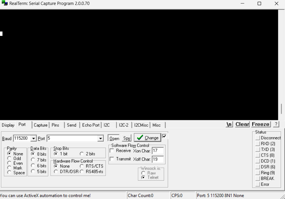
UART Settings
Baud Rate: 115200
Data Bit(s): 8
Stop Bit(s): 1
Parity: None
Flow Control: None
Endianness: Little (LSB first)
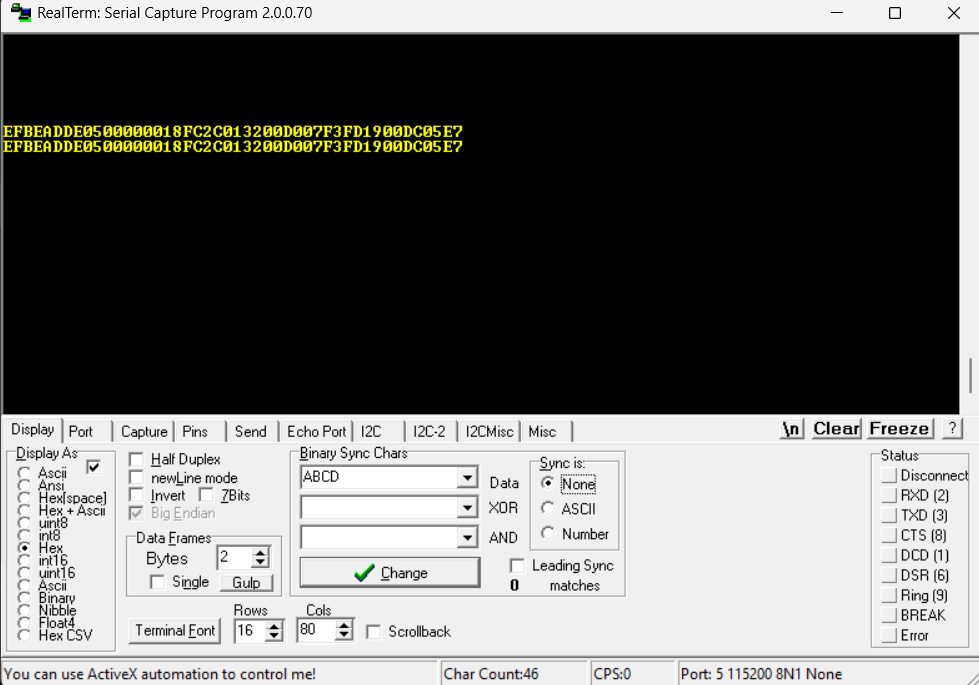
Host To RoverGen2: Command Frame Format
The Command frame consists of the 4-byte preamble (0xDEADBEEF), command ID, mailbox data and the 8-bit CRC, for a total of 27 bytes.
0
Preamble XLSB
0xEF
1
Preamble LSB
0xBE
2
Preamble MSB
0xAD
3
Preamble XMSB
0xDE
5
Command MSB
6
Mailbox Byte 0
...
...
25
Mailbox Byte 19
26
8-bit CRC
RoverHatGen2 To Host: Command Response Frame Format
The Command Response frame is solicited; it is generated on each received Command frame from the host.
It consists of the 4-byte preamble (0xDEADBEEF), the Command ID which generated the Command Response frame, the Response ID itself, IMU data, TOF distance data, and the 8-bit CRC, for a total of 23 39 bytes.
It is highly recommended that the Host await the Command Response, before sending any subsequent Command frames.
0
Preamble XLSB
0xEF
1
Preamble LSB
0xBE
2
Preamble MSB
0xAD
3
Preamble XMSB
0xDE
5
Command MSB
7
Response MSB
8
Accel X LSB
int16
9
Accel X MSB
10
Accel Y LSB
int16
11
Accel Y MSB
12
Accel Z LSB
int16
13
Accel Z MSB
14
Gyro X LSB
int16
15
Gyro X MSB
16
Gyro Y LSB
int16
17
Gyro Y MSB
18
Gyro Z LSB
int16
19
Gyro Z MSB
20
TOF Distance LSB
uint16
21
TOF Distance MSB
22
Motor 1 Current XLSB
float
23
Motor 1 Current LSB
24
Motor 1 Current MSB
25
Motor 1 Current XMSB
26
Motor 2 Current XLSB
float
27
Motor 2 Current LSB
28
Motor 2 Current MSB
29
Motor 2 Current XMSB
30
Motor 3 Current XLSB
float
31
Motor 3 Current LSB
32
Motor 3 Current MSB
33
Motor 3 Current XMSB
34
Motor 4 Current XLSB
float
35
Motor 4 Current LSB
36
Motor 4 Current MSB
37
Motor 4 Current XMSB
38
8-bit CRC
CRC Generation
The CRC appended to the Command and Command Response frames is an 8-bit XOR CRC:
The CRC is computed across the payload data of the frame, EXCLUDING the preamble.
For example: Bytes 4 to 25 of the Command Frame and bytes 4 to 21 of the Command Response Frame.
UART Interface Debug
RealTerm overview from Sparkfun.
Can be downloaded here.
Set Motor 1 and Motor 2 Throttles (Command 0x0005) Example
Motor 1 Throttle: 50 %
Motor 2 Throttle: -100%
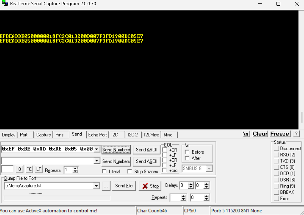
Set All Motor Throttles (Command 0x0013) Example
Sets motors 1-4 to 100 % throttle.
Kill All Motors (Command 0x0007) Example
Set Motor 1 Throttle (Command 0x0003) Example
Sets motor 1 to 100 % throttle.
Set All Motor Throttles (Finite) (Command 0x0014) Example
Motor 1: Unchanged
Motor 2 : 100 % throttle for 5 seconds
Motor 3: 50 % throttle, indefinately
Motor 4: -25 % throttle for 10 seconds